STA 1-11-24 E-KE 230 V/3~ AWG 25.4 mm – CS 320 FU-I – 7.0 m
Prices are only visible after login.
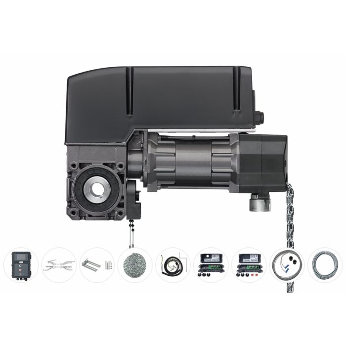
Scope of delivery:
- Operator´ STA 1-11-24 E-KE 230 V/1~ FU/I AWG 25.4 mm with 1,000 mm reel chain
- CS 3 20FU/I 230V/1PH control unit in CS standard housing with 3-way push-button and LC display in the cover, connection cable with type F earthed plug
- Cable set with connection terminals and cable glands in control unit and drive, 7,000 mm
- Reel chain: 11,000 mm, with 2 chain locks
- Torque support 1 L-shape
- STA Standard accessory bag
- Spiral cable 5x0.25 mm² with mounting bracket, cable glands, connection terminals for the control unit and plug for the door leaf junction box, 1,600 mm uncoiled/800-3,200 mm coiled length
- Door leaf junction box with circuit board, opening for spiral cable and 4 cable entries
- Door leaf junction box with circuit board with connections for conventional safety elements, IP54, without cover opening for spiral cable
- Connection cable for connecting 2 door leaf junction boxes, 10 m
- F photoelectric sensor transmitter 10,500 mm/receiver 1,000 mm with 2 F spacer sleeves 11/22 mm
Operator – Features:
- Die-cast aluminum housing, rolled worm shaft and double worm shaft bearings
- Emergency operation via emergency hand crank (KU), emergency hand chain (KE), emergency release (E), emergency release with spring return (E-FR) or maintenance release with emergency hand chain (E-KE)
- Maintenance release optional
- Easy conversion from crank to chain
- Hollow shaft 25.4 mm as standard, special hollow shaft on request
- Supply: 230 V/1~/50 Hz
- Thermal protection in the motor winding
- For gate systems with above-average circuits, a operator with an increased motor duty cycle (HD) should be selected
- Pluggable connections (control side)
- End position setting via electronic absolute encoder (AWG) or mechanical limit switches (MEC)
- Version with integrated frequency converter and external control. Supply: 230 V/1~, frequency: 50/60 Hz, control voltage: 24 V-DC
- The soft-start and soft-stop technology ensures a longer service life of the door system, as the door mechanism is subjected to less stress. This reduces repair costs.
- Special variants such as further voltages and frequencies, higher protection classes and hollow shaft Ø on request
- When the output speed is increased (operation with frequency converter), the output torque is reduced. In this case, the following applies: An increase of the output speed by 10 % causes a reduction of the output torque by 5 %.
- For temperature ranges below -20 °C there is suitable oil and electric heating on request
Control – Functions:
- Speed-independent control of gates
- Start and end speed separately adjustable for both running directions
- Additionally 2nd final speed adjustable in running direction CLOSE
- Acceleration and deceleration times adjustable for both directions
- Acceleration and deceleration times for actuation of travel command, stop command, closing edge safety device and light barrier can each be set separately
- Braking points freely selectable/adjustable braking deceleration
- Adjustable power values for adaptation to the motor
- 4 programmable relay outputs with 44 functions
- 2 programmable inputs with 27 functions
- Rotation direction monitoring and detection (only with AWG)
- Integrated gate run counter
- Programmable maintenance alarm (PIN code protected)
- Integrated error memory (readout of all error messages indicating frequency and cycle of last occurrence) only with LCD monitor
- Changing the direction of rotation via circuit board push button/display
- Adjustable power limitation in OPEN direction (only with AWG)
- Intermediate position programmable (only with AWG)
Control – End position setting:
- Via mechanical limit switches (MEC) and/or via absolute encoders (AWG)
- Setting via LC monitor
Control – Operation:
- Circuit board push buttons and LEDs for status indication (standard)
- Pluggable LC display with plain text display
- 3-button navigation/status and diagnostic messages
Control – Structure and connection:
- Short-circuit proof extra-low voltage
- Supply for external devices (24 V-DC/500 mA and 230 V-AC/1 A)
- Illuminated cover keypad (night illumination)
- Housing protection for printed circuit board
- Adjustable, preassembled wall brackets
- Connection for elements of the safety circuit
- Connection for closing edge protection (opto, 8.2 kOhm, pressure wave bar or leading light barrier) in CLOSE direction
- Connection for closing edge protection (8.2 kOhm and opto) in OPEN direction
- Connection for 2 light barriers (2-wire, relay, NPN, PNP) with/without testing
- Connection for wicket door and slack rope switch PL c cat. 2 (8.2 kOhm) with testing according to EN 12453:2017
- Connection for 2 light grid systems with/without testing
- Interface for connecting expansion modules
- Slots for radio module and weekly timer
- Slot for 2-channel radio transmission system for wireless signal transmission of closing edge system and/or safety circuit
- Control of the magnetic brake via relay output
- For operators with externally switched brake, a brake monitoring module is additionally installed (BWM1)
- Interface for connecting a frequency converter
- Switchable transformer from 230 V/1~/3~ to 400 V/3~
- Pluggable LC display with plain text display
Control – Optional:
- MS-Bus extension module two-way traffic control
- MS-Bus extension module pull-in safety device
- Integrated main switch
- Customized cover lamination
- Frequency converter integrated in operator (FU-I version without brake, only 0.75 kW)
- Control in steel cabinet
* The values given were determined for an even distribution of the cycles. A cycle consists of two movements (opening and closing) and has a deflection of 10 revolutions of the output shaft in each direction. At ambient temperatures between 40°C and 60°C, a reduction of the maximum cycles per hour by 50% must be taken into account.
** For vertically moving doors and roller shutters, a reduction of the specified pull force by a further 20% may be necessary. Possible reasons for this are, for example, additional seals, double-walled profiles or an unfavorable winding ratio where the door height exceeds the door width. In addition, it should be noted that the maximum torque only occurs after one to two revolutions when thick or high profiles are used.
*** Alternative limit switch ratios are available upon request.
Remser Brook 11
33428 Marienfeld
For questions to the manufacturer, please use this Contact form.
")